|
Penetrating Probe Introduction
As the probes are falling into the atmosphere to a maximum distance of 420 km, it is important to choose a communications frequency that will result in a small signal attenuation as it travels upwards through the atmosphere, but also a frequency that is large enough so that it can overcome the large free-space propogational losses to the relay satellite.
Given the attenuation data for 2 km slices of atmosphere for various frequencies, Excel ( download worksheet) was used to find the total attenuation from each probe as it reached the 420 km distance from the top of the atmosphere. It is important to note that the off-angle probes will have more atmospheric attenuation to overcome in addition to a larger free-space distance to travel, so picking a frequency will be based off of this worst case scenario. As discussed in Section Initial Research » Calculations, the angle between the satellite and the top of the atmosphere was calculated to be 14.86º. However, as the probe continues to fall, this angle decreases, forcing the transmission signal to travel through more than 2 km of each slice of atmosphere. download worksheet) was used to find the total attenuation from each probe as it reached the 420 km distance from the top of the atmosphere. It is important to note that the off-angle probes will have more atmospheric attenuation to overcome in addition to a larger free-space distance to travel, so picking a frequency will be based off of this worst case scenario. As discussed in Section Initial Research » Calculations, the angle between the satellite and the top of the atmosphere was calculated to be 14.86º. However, as the probe continues to fall, this angle decreases, forcing the transmission signal to travel through more than 2 km of each slice of atmosphere.

Figure 1: Attenuation Curves for Probe (Angle = 0º)
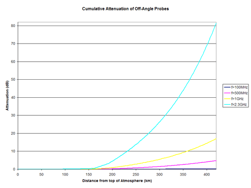
Figure 2: Attenuation Curves for Probe (Angle = 45º, -45º)
Figures 1 and 2 refer to the total attenuation of various frequencies for both the zero-degree probe as well as the off-angle probes. As you can see in Figure 2, even with the increased distance of travel through the atmosphere, the attenuations do not increase drastically from the results shown in Figure 1.
An important trade-off calculation is to determine whether to use a carrier frequency of 500 MHz or 1.0GHz. While the attenuation through the atmosphere was clearly higher for the 1.0 GHz frequency, it was uncertain what the propogational losses were for 500 MHz. A quick calculation revealed that the lower atmospheric attenuation at 500 MHz was greater than the decreased propogational losses at 1 GHz, so it was decided that the probes will communicate with the relay satellite at a frequency of 500 MHz.
The cost of any space mission is an important component in all aspects of spacecraft design. Since there are three probes falling into the atmosphere, it would be costly to have to design three different probes that operate at different frequencies (FDMA); it would be even more costly and difficult to have each probe broadcast at the same frequency, but at different time intervals (TDMA), especially due to the synchronization problems that can occur.
The result was to use a Spread Spectrum protocol, in which the data is combined with a pseudo-noise signal and transmitted on a carrier frequency. Each of the three probes could be built identically, except that the pseudo-noise generator would be phase shifted to allow for proper demodulation at the relay satellite. In addition to being able to produce identical probes, using spread spectrum can actually provide additional gain at the receiver by spreading out data over a larger bandwidth. Because the probes are limited in power, spread spectrum will be used to provide extra gain without the expense of having to provide extra transmit power.
Powering the probe is a small fuel cell, capable of producing a radio transmission at 20W. Using a dish antenna on the probe, the probe will have to be stabilized as it falls into the dense atmosphere in order to allow a motorized control system to point the dish at the relay satellite overhead.
Next Section »
References: |