|
Probe Design
Figure 1: Block Diagram of Probe Transmitter
Figure 1 shows the block diagram of the communications link for the probe. The source of data comes at an uncompressible stream at a data rate of 8 kbps.
Forward Error Correction (FEC) is a system of error control by which redundancy is added to the information being transmitted using a predetermined algorithm. One of the most recently developed forms of FEC is called turbo coding, which combines convolutional codes with an interleaver to produce a code that can perform within a fraction of the Shannon limit, which states the maximum efficiency of error correction methods [1].
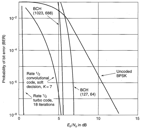
Figure 2: Bit Error Rate and C/N combinations for various coding methods. [2]
The graph in Figure 2 shows the Bit Error Rate (BER) achieved by using various coding sequences at various carrier to noise (C/N) ratio. From this graph, it is evident that an error-free communications channel can be achieved by using turbo code correction and operating at a C/N ratio of just a few dB. [2]
The turbo code modulator for this design uses a rate 1/2 code, which effectively doubles the data rate from 8kbps to 16 kbps.
Spread Spectrum, as seen in the Introduction, is a means by which a signal can be distributed along a larger bandwidth by multiplying the original signal by a pseudo-noise code. In addition to achieving gain at the receiver, the power requirement of the transmitter is greatly reduced. Using a pseudo-noise chip rate of 1.023 Mchips/second, the effective data rate becomes 1.023 Mbps. The linear despreading gain is determined by
![FormBox[RowBox[{M, =, RowBox[{T_chip/T_data, =, RowBox[{RowBox[{RowBox[{(, RowBox[{1.023, , M, , chips/sec}], )}], /, (16 k bits/sec)}], =, 65.472}]}]}], TraditionalForm]](/mathematica/HTMLFiles/index_9.gif)
The spreaded signal will then go through a Bi-polar Phase Shift Keying (BPSK) modulator, which takes the digital signal and modulates it into an analog signal of varying voltage on the in-phase channel. A digital 1 results in a positive voltage whereas a digital 0 results in a negative voltage. This method was chosen over QPSK (Quadrature Phase Shift Keying) because it is uncertain how the atmosphere of Neptune will affect the phase of the transmitted signal and could lead to errors. Additionally, since the data rate (1.023 Mbps) is not extremely high, BPSK should be able to handle and accurately transmit the data stream.
Included in the BPSK modulator is a pulse shaper; as a signal is being converted from digital to analog for transmission, it is important to choose a pulse that is bandwidth-friendly and satisfies the Nyquist ISI Criterion, which states that the residual amplitudes of the pulse must be zero at all other sampling periods. This ensures that only one pulse magnitude will be present at any bit interval. The pulse shaper module that is included in the BPSK modulator uses a raised root cosine pulse with variable roll-off factor. Using MATLAB and the solutions to the class homework [3], a roll-off factor of 40% was chosen along with the bandwidth of the current signal. The bandwidth is estimated to be approximately 2.046 MHz, as is seen with the pulse in Figure 3.
Figure 2: Pulse Shape and Bandwidth
A local oscillator and a multiplier are used to put the data signal onto a carrier frequency of 500 MHz. An ultra-low jitter oscillator was used that has an error of 50 parts per million (ppm). In order to eliminate any unwanted noise or stray signal in the path, a low-noise bandpass filter with a band of 4 MHz (498 to 502 MHz) is used.
The last portion of the transmitter link is the amplification stage. It is always important to amplify the signal as much as possible before transmitting the data through the antenna. A large power amplifier, capable of a constant 10W output is used. The signal is then transmitted through a 1.2 meter wide dish antenna with a gain of 21.284 dBi at 500 MHz.
As the probe falls into the atmosphere, Doppler shifting must be considered. Doppler shifting is the "effect on electromagnetic wavelengths emitted by a source at a distance that is increasing or decreasing in relation to the observer. If the distance is increasing, the wavelengths are 'stretched,' and if the distance is decreasing, the wavelengths are 'squeezed.'" [4] The maximum Doppler shift can be determined by

Where V is the velocity of the source with respect to the observer (the probe with respect to the relay satellite) and  is the frequency of the transmitted source (0.599585). From the project specification, the probe descends to a distance of 420 km into the atmosphere over a period of 50 hours, which translates into a velocity of -2.333 is the frequency of the transmitted source (0.599585). From the project specification, the probe descends to a distance of 420 km into the atmosphere over a period of 50 hours, which translates into a velocity of -2.333 under the assumption that the relay satellite is always in a constant position with respect to the probe (it is in GNO). The Doppler shift is then under the assumption that the relay satellite is always in a constant position with respect to the probe (it is in GNO). The Doppler shift is then
 = =![FormBox[RowBox[{RowBox[{RowBox[{(, RowBox[{RowBox[{-, 2.333}], m/s}], )}], /, RowBox[{(, RowBox[{0.599585, m}], )}]}], =, RowBox[{RowBox[{-, 3.89158}], Hz}]}], TraditionalForm]](/mathematica/HTMLFiles/index_14.gif)
At such a slow velocity going into the atmosphere, the Doppler shift experienced by the relay satellite is not significant, as the local oscillators have a greater error than this shift.
Next Section »
References:
1. The Free Dictionary (http://encyclopedia.thefreedictionary.com/Forward%20error%20correction)
2. Pratt, Bostian, Alnutt. Satellite Communications, Second Edition. Copyright 2003.
3. ECE6390 Home Page (http://www.propagation.gatech.edu/ECE6390), Dr. Greg Durgin
4. Astronomy Fact Guru (http://www.site.uottawa.ca:4321/astronomy/index.html) |