|
Link with Probe

Figure 1: Block Diagram of Link between Probe and Receiver
Figure 1 shows the block diagram of the communications receiver link for the relay satellite. The source of data will be coming from the three probes that are descending into the atmosphere.
The most important step in a receiver is to amplify the signal coming in on the dish antenna. Low Noise Amplifiers (LNA) are high quality amplifiers that inject little noise into the system. It is typical that the first stage of amplification on a communications link is from a LNA. It is unfortunate that any noise in the signal gets amplified, too. Therefore, a bandpass filter is used.
The bandpass filter filters out any unwanted noise on all frequencies except that of the carrier frequency of 500 MHz. This filter attempts to clean up the signal before it is stepped down to its baseband signal.
Using a local oscillator and a multiplier, the signal is stepped down to its baseband frequency. Another bandpass filter is used to eliminate the high frequency signals that appear as a result from the multiplier.
A BPSK Demodulator takes an analog signal, which should be pulsed with a Nyquist ISI-shaped pulse, and converts it back into a digital form. Recall from the previous sections that a BPSK modulated signal has two values, a positive voltage to denote a digital 1, and a negative voltage to denote a digital 0. It was predicted that BPSK would be more reliable than QPSK due to the uncertainty of the Neptunian atmosphere.
One of the benefits of using Spread Spectrum is that many different users can use the same frequency band and not cause any interference or problems with decoding the signal. As mentioned before, a signal is mixed with a pseudo-noise sequence that is unique to that particular user (or a particular phase of a common pn sequence). When this spreaded signal is multiplied by the same sequence, the signal despreads and is recognizable. In the case of the relay satellite, there are three probes transmitting data back to the satellite. Therefore, a common pseudo-noise sequence can be used among all three probes, however each probe will start at a different interval in the sequence.
In addition, spread spectrum can give a despreaded signal a large processing gain. In the case of the relay satellite and probe, with a chip rate of 1.023 Mbps and a FEC-coded data rate of 16 kbps, the processing gain is calculated by
![FormBox[RowBox[{M, =, RowBox[{T_chip/T_data, =, RowBox[{RowBox[{RowBox[{(, RowBox[{1.023, , M, , chips/sec}], )}], /, (16 k bits/sec)}], =, 65.472}]}]}], TraditionalForm]](/mathematica/HTMLFiles/index_18.gif)
The three despreaded signals are then sent into a Turbo Code Demodulator, which will use the redundancies that are added into the signal to remove any errors that might have been caused throughout the transmission. The final output will be the original 8 kbps signal which is then stored on a solid state data storage device. As will be seen in the calculations, if the C/N ratio is higher than about 3dB, the received signal should have been successfully demodulated by the turbo code demodulator without any error.
The Half Power BeamWidth (HPBW) is a measurement to describe the "angle across the main lobe of an antenna pattern between the two directions where the sensitivity of the antenna is half the value at the center of the lobe." [1] Recall that the maximum angle from the vertical that the probes will be with respect to the relay satellite (see Initial Research » Calculations) is 14.8606°. The HPBW of a dish antenna can be approximated by
Since the dish antenna is round, 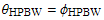 . Therefore . Therefore
![FormBox[RowBox[{θ_HPBW, =, RowBox[{RowBox[{RowBox[{(30, 000), /, RowBox[{10, ^, RowBox[{(, RowBox[{21.284, /, 10}], )}]}]}], ^, (1/2)}], =, RowBox[{14.9403, °}]}]}], TraditionalForm]](/mathematica/HTMLFiles/index_21.gif)
This angle means that the dish antenna on the receiver satellite will be able to retrieve the data from the probes inside the HPBW of 14.8606º (calculated in Initial Research » Calculations), at which the received power will be greater. If the angle of transmission from the probe was outside this HPBW, the received signal would be significantly less.
Next Section »
References: |